Oscilloscopes are one of our favorite tools for electronics development. They make the hidden dances of electrons visually obvious to us, and give us a clear understanding of what’s actually going on in a circuit.
The question few of us ever ask is, how do they work? Most specifically—how do you design a circuit that’s intended to measure another circuit? Aleksa Bjelogrlic has pondered that very idea, and came down to explain it all to us at the 2023 Hackaday Supercon.
All Up Front

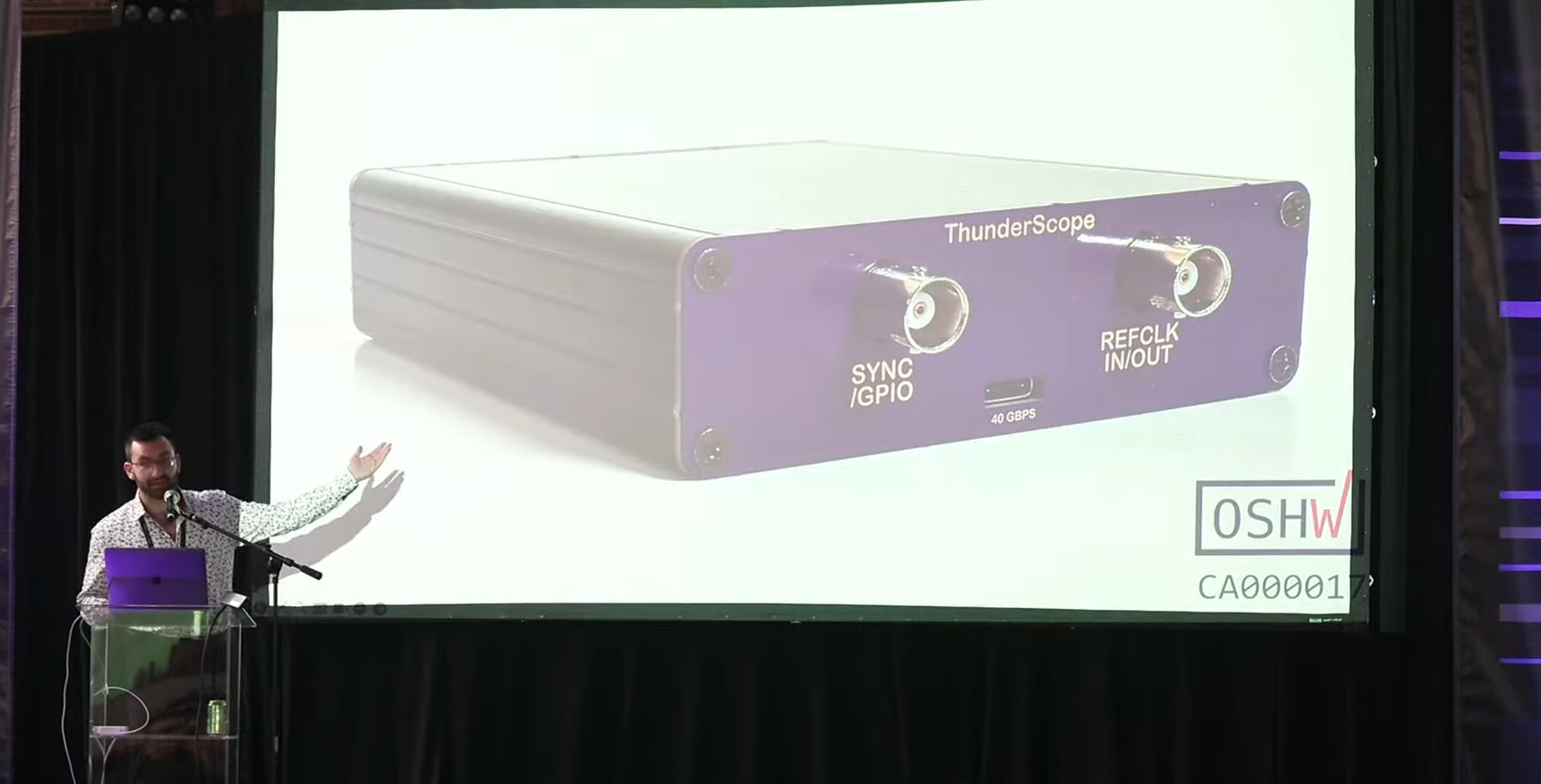
Aleksa has spent five years designing an open-source oscilloscope known as the ThunderScope. He wanted an oscilloscope that could measure a circuit while streaming out samples at speed to a computer, so he decided to build his own. His idea was to put the analog part of a high-speed scope in a box, while offloading the digital processing to an attached computer. This would allow the software side of things to be regularly updated to stay with the times. It would be easy to add new triggers or protocol decoders to the setup without having to mess with the hardware.
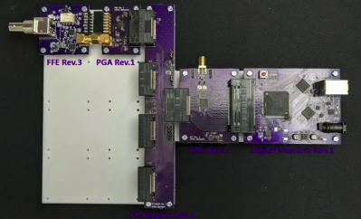
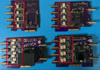
His early experiments saw him streaming samples from a test scope he built, but it wasn’t perfect. He used USB 3 Gen 1, but it was only giving him 350 MB/s transfer rates. He needed closer to 1 GB/sec to properly stream samples of high-speed signals. He also had issues with his front-end design, with poor frequency response. He soon switched over to PCI-Express for higher transfer rates, and built a new scope with a better front-end. This was the first revision of ThunderScope. Later revisions improved the front end further, tackled clock-generator issues, and generally refined the design into something more functional and useful.

The development process is mere context, though. The real purpose of Aleksa’s talk was to dive into the nitty gritty of oscilloscope front-end designs. While his scope has had four major revisions, the front end has had over a dozen updates. The front end’s job is to take an analog signal, and finesse it into something that the scope’s analog-to-digital converter can actually handle. It’s job is, in part, to act as an electrical interface to allow the scope to measure all kinds of different signals. Aleksa explains that it can allow you to view AC signals superimposed on large DC voltages, or measure large signals beyond the voltage range of the scope’s ADC. It can also help scale signals that might otherwise be out of range for the ADC itself.
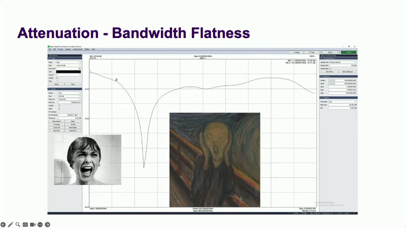
Aleksa explains input impedance, capacitance of the front end, and why you have to compensate a probe to suit your individual scope. He also covers the eternal challenge facing the designer—minimizing noise while maximising bandwidth, while also maintaining a flat response from DC all the way up to high frequency signals. And of course, you need to be able to measure and quantify how your front end is performing, so Aleksa dips into the basics in that regard.
AC and DC coupling is also covered. This is critical for when you want to look at an AC waveform without all that annoying DC bias in the way. Naturally, this is achieved with an in-line capacitor, which blocks DC while allowing the AC component to pass. Then there’s the helpful discussion about how resistors come with stray capacitance and inductance “for free”—and capacitors in turn come with resistance and inductance, too. When you’re chasing around weird dips in your response curve, you’ve got to be across these things.

If you’ve ever considered creating your own oscilloscope from scratch, Aleksa’s talk is a great primer. It’s really useful stuff. After all, getting the front end right is as important as getting the right tires on your car. If it’s not up to the task, all your measurements will be suspect from the drop. It’s a deep and rich topic, and one that you could spend years studying in detail. Indeed, Aleksa has, and his work on the ThunderScope is the ultimate proof of that.
