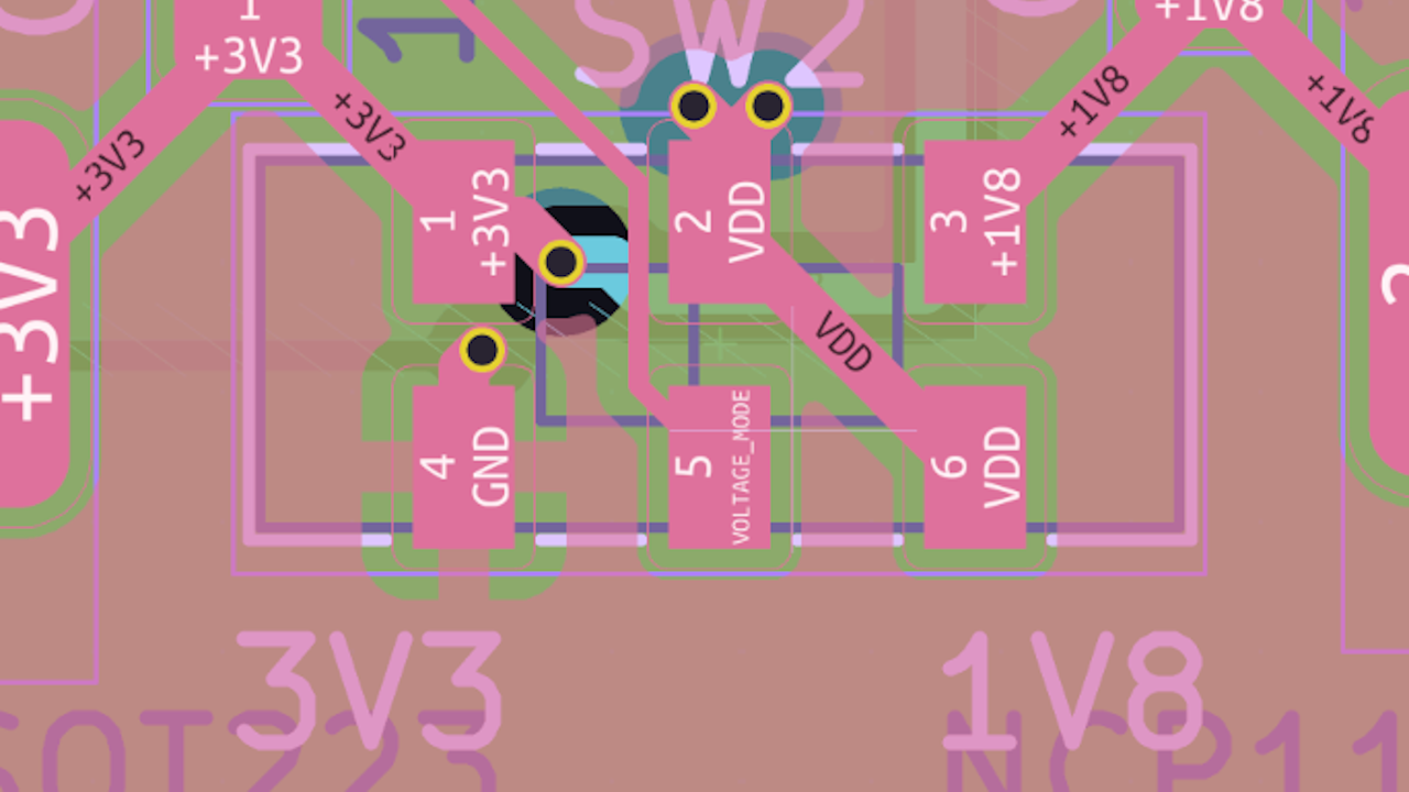
Ever want to build a RP2040 devboard that has everything you could ever want? Bad news, “everything” also means adding 1.8 V GPIO voltage support. The good news is that this write-up by [xenia] explains the process of adding a “3.3 V/1.8 V” slide switch onto your board.
Some parts are obvious, like the need to pick a flash chip that works at either voltage, for instance. Unfortunately, most of them don’t. But there’s more you’d be surprised by, like the crystal, a block where the recommended passives are tuned for 3.3 V, and you need to re-calculate them when it comes to 1.8 V operation – not great for swapping between voltages with a flick of a switch. Then, you need to adjust the bootloader to detect the voltage supplied — that’s where the fun begins, in large part. Modifying the second stage bootloader to support the flash chip being used proved to be quite a hassle, but we’re graced with a working implementation in the end.
All the details and insights laid out meticulously and to the point, well-deserved criticism of Raspberry Pi silicon and mask ROM design choices, code fully in Rust, and a success story in the end – [xenia]’s write-up has all you could wish for.
Want to learn more about the RP2040’s bootloader specifically? Then check this out — straight out of Cornell, a bootloader that’s also a self-spreading worm. Not only is it perfect for updating your entire RP2040 flock, but it also teaches you everything you could want to know about RP2040’s self-bringup process.
