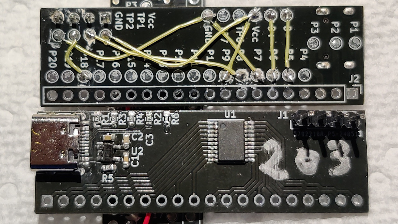
There are so many new cool MCUs coming out, and you want to play with all of them, but, initially, they tend to be accessible as bare chips. Devboards might be hard to get, not expose everything, or carry a premium price. [Willmore] has faced this problem with an assortment of new WCH-made MCUs, and brings us all a solution – a universal board for TSSOP20-packaged MCUs, breadboard-friendly and adaptable to any pinout with only a few jumpers on the underside.
The board brings you everything you might want from a typical MCU breakout – an onboard 3.3V regulator, USB series resistors, a 1.5K pullup, decoupling capacitors, and a USB-C port. All GPIOs are broken out, and there’s a separate header you can wire up for all your SWD/UART/USB/whatever needs – just use the “patch panel” on the bottom of the board and pick the test points you want to join. [Willmore] has used these boards for the CH32Vxxx family, and they could, no doubt, be used for more – solder your MCU on, go through the pin table in the datasheet, do a little point-to-point wiring, and you get a pretty functional development board.
Everything is open-source – order a few of these boards from your fab of choice, and you won’t ever worry about a breakout for a TSSOP20 MCU or anything that would fit the same footprint. It could even be used in a pinch for something like an I2C GPIO expander. This is also a technique worth keeping in mind – a step above the generic footprint breakouts. Looking for more universal breakouts to keep? Here’s one for generic LCD/OLED panel breakouts.
